Fluid Kinematics
- Fluid Kinematics deals with the motion of fluids such as displacement, velocity, acceleration, and other aspects. This topic is useful in terms of the exam and the knowledge of the candidate.
- Kinematics is the branch of classical mechanics that describes the motion of bodies and systems without consideration of the forces the cause the motion.
Types of Fluid Flows
Fluid flow may be classified under the following headings;
Steady & Unsteady Flow

Uniform & Non-uniform Flow
- Steady uniform flow
- Conditions do not change with position in the stream or with time.
- E.g. flow of water in a pipe of constant diameter at a constant velocity.
- Steady non-uniform flow
- Conditions change from point to point in the stream but do not change with time.
- E.g. Flow in a tapering pipe with the constant velocity at the inlet.
- Unsteady uniform flow
- At a given instant in time the conditions at every point are the same but will change with time.
- E.g. A pipe of constant diameter connected to a pump pumping at a constant rate which is then switched off.
- Unsteady non-uniform flow
- Every condition of the flow may change from point to point and with time at every point.
- E.g. Waves in a channel
Flow Pattern
Three types of fluid element trajectories are defined: Streamlines, Pathlines, and Streaklines.
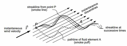
- Pathline is the actual path travelled by an individual fluid particle over some time period. The pathline of a fluid element A is simply the path it takes through space as a function of time. An example of a pathline is the trajectory taken by one puff of smoke which is carried by the steady or unsteady wind.
- Timeline is a set of fluid particles that form a line at a given instant.
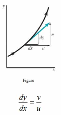
- Streamline is a line that is everywhere tangent to the velocity field. Streamlines are obtained analytically by integrating the equations defining lines tangent to the velocity field as illustrated in the figure below:
where u,v, and w are the velocity components in x, y and z directions respectively as sketched
- Streakline is the locus of particles that have earlier passed through a prescribed point.A streakline is associated with a particular point P in space which has the fluid moving past it. All points which pass through this point are said to form the streakline of point P. An example of a streakline is the continuous line of smoke emitted by a chimney at point P, which will have some curved shape if the wind has a time-varying direction
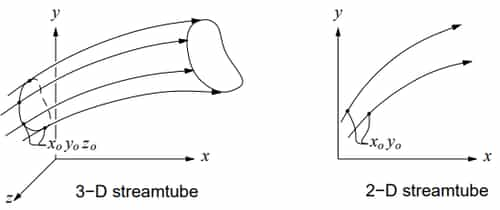
- Streamtube: The streamlines passing through all these points form the surface of a stream-tube. Because there is no flow across the surface, each cross-section of the stream tube carries the same mass flow. So the stream tube is equivalent to a channel flow embedded in the rest of the flow field.
Note:
- The figure below illustrates streamlines, pathlines, and streaklines for the case of smoke being continuously emitted by a chimney at point P, in the presence of shifting wind.
- In a steady flow, streamlines, pathlines, and streaklines all coincide.
- In this example, they would all be marked by the smoke line.
Velocity of Fluid Particle
- Velocity of a fluid along any direction can be defined as the rate of change of displacement of the fluid along that direction
- Let V be the resultant velocity of a fluid along any direction and u, v and w be the velocity components in x, y and z directions respectively.
- Mathematically the velocity components can be written as
u = f ( x, y, z, t )
w = f ( x, y, z, t )
v = f ( x, y, z, t )
- Let VR is resultant velocity at any point in a fluid flow.
- Resultant velocity VR = ui + vj + wk
Where u=dx/dt, v=dy/dt and w=dz/dt are the resultant vectors in X, Y and Z directions, respectively.
Acceleration of Fluid Particle
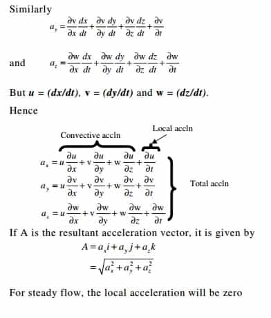
- Acceleration of a fluid element along any direction can be defined as the rate of change of velocity of the fluid along that direction.
- If ax , ay and az are the components of acceleration along x, y and z directions respectively, they can be mathematically written as ax = du/ dt.
Stream Function
- The partial derivative of stream function with respect to any direction gives the velocity component at right angles to that direction. It is denoted by ψ.
- The continuity equation for two-dimensional flow is
Equations of Rotational Flow
- As ψ satisfies the continuity equation hence if ψ exists then it is a possible case of fluid flow.
- Rotational components of fluid particles are:
Equation of Irrotational Flow
- If ωx = ωy = ωz then, flow is irrotational.
- For irrotational flow, ωz = 0
- This is the Laplace equation for ψ.
Note: It can be concluded that if stream function (ψ) exits, it is a possible case of fluid flow. But we can’t decide whether the flow is rotational or irrotational. But if stream function ψ satisfies the Laplace equation then, it is a possible case of irrotational flow otherwise it is rotational flow.
Velocity Potential Function
- It is a scalar function of space and time such that its negative derivative with respect to any direction gives the fluid velocity in that direction. It is denoted b φ
We know that the continuity equation for steady flow is
- If φ satisfies the Laplace equation, then it is a possible case of fluid flow.
Rotational component ωz can be given by
- It shows that φ exits then, the flow will be irrotational.
Relation between Stream Function and Velocity Potential
We know,
and


Comments
Post a Comment